Despite their name and shape, these rollers, which bear significant loads, cannot help sliding on the ramps they abut on.
Sliding under load creates friction and causes wear.
The current way to reduce friction and wear is the use of low-friction self-lubricated nylon / plastic material.
What if instead of sliding, the rollers were true Rolling-Rollers?
This is what the PatRoR does.
In the following animation, the drive pulley is shown at three different ratios, a long (overdrive), a medium and a low.
Each Rolling-Roller comprises a pair of coaxial rollers (the one is a spool roller in this specific case) rotatably mounted to each other.
The relative rotation of the two rollers of each Rolling-Roller is shown:
In the following animation the drive pulley is at a low ratio:
Here is exploded a conventional drive pulley for CVTs:
and here is the same drive pulley modified to PatRoR:
All it takes for the modification is the replacement of the sliding-roller-weights by Rolling-Rollers, and the machining of a groove on each ramp of the ramp plate (a work that requires neither accuracy nor special tools).
The PatRoR is the substitution of the conventional frictionfull sliding wedge by a frictionless rolling wedge.
PatEff CVT
In the SECVT (Suzuki Electronically-controlled Continuously Variable Transmission), which is regarded as the state-of-the-art CVT for lightweight vehicles, a servomotor under the control of the ECU (Electronic Control Unit) displaces axially the slidable half of the front pulley and selects the transmission ratio.
As the effective diameter of the front pulley varies, the rear pulley (under the action of the "constant length" V-belt) adjusts its effective diameter.
The following plot (click here for the "same" plot in pdf format):
shows the Efficiency of the SECVT vs. the Load; the Over-Clamping is shown by the color bars (the data are from lab tests made in the Eindhoven University for a "Formula Student Racecar" project: click SECVT for more).
Compare the "efficiency fall" with the "over clamping" of the belt.
The control of the transmission ratio by the SECVT is sophisticated (the ECU controls precisely the axial displacement - i.e. the distance from the casing - of the slidable half of the front pulley); the opposite is true for the "control" over the V-belt clamping (the spring of the rear pulley does what it "likes", not what it "should"):
In the "0% LOAD" curve of the above plot the torque-cam action is zero.
In the "25% LOAD", "50% LOAD" and "100% LOAD" curves, the thrust force caused by the "torque-cam" is added to the thrust force provided by the compressed spring of the rear pulley.
These curves are the "lab measured" ones.
A safety factor (like 30%) is necessary to avoid a "belt slipping" at all operational conditions.
The dashed lines S1, S2, S3 and S4 are "theoretical" and give the "necessary" thrust force for 100%, 50%, 25% and 0% load respectively (necessary in the sense that with such a thrust force there is no belt slipping; in the following it will be clarified how these lines result).
The left end of the "100% LOAD" "lab measured" curve is 30% higher (safety factor) than the left end of the S1 line.
The right end of the S1 line is 50% lower than the left end of the S1 line because at the highest gear, at right, the eccentricity of the V-belt in the front pulley is double as compared to the eccentricity of the V-belt in the front pulley at the lowest gear, at left.
In order to pass only 50% of the load, the necessary thrust force is half as compared to the 100% load case. This way the S2 line results from the S1 line. And so on for the S3 and S4 lines.
For a specific load (input torque) and gear ratio the difference between the "lab measured" curve and the "theoretical" one, gives the "over clamping", i.e. the surplus of thrust force that unnecessarily loads the V-belt.
For instance, between 25% and 50% load, at high gear (overdrive), i.e. wherein most of the time a typical CVT operates, the over clamping is between 250% and 600%, which means that the V-belt is compressed 2.5 to 6 times more than what is required in order to pass - without belt slipping - the input torque to the output shaft (according the "Efficiency vs. Load" plot, the efficiency of the CVT at these conditions is around 80%).
The following figure shows at top the radial forces caused on the V-belt by the thrust forces the conical pulleys apply on the V-belt.
The total radial force on the V-belt at the one pulley side needs to be equal with, and opposite to, the total radial force acting on the V-belt at the other pulley side, as in the figure above. At the low gear case at left, a 150Kp thrust force is applied on the rear (bottom left) pulley by the "rear pulley spring" and causes a total radial force of 50Kp on the V-belt. The front pulley needs to apply an opposite 50Kp total radial force onto the V-belt, which means the control mechanism (supported on the casing) has to apply, to the slidable half of the front pulley, a thrust force of about 150Kp.
Multiplying the eccentricity R1 of the V-belt at the front pulley by the coefficient of friction (Cf) between the V-belt and the front pulley and by the thrust force (TF, 150Kp in this case) and by 2 (there are two conical halves wherein the V-belt abuts on, and receives force from) it results the torque capacity Mc of the CVT, i.e.
Mc=R1*Cf*TF*2
The torque M provided by the engine to the CVT input shaft must not exceed the Mc (case without a torque-cam mechanism).
In the high gear case (at right) the eccentricity R2 has been doubled (the R2 is about twice as big as the R1), which means that the necessary thrust force TF is half (i.e. 75Kp) in order to maintain the same torque capacity Mc; however, the spring of the rear pulley is now compressed, resulting in a substantially heavier thrust force (180Kp), which gives a proportionally higher total radial force (60Kp) on the V-belt, which overloads the V-belt at the front pulley by a proportionally heavier thrust force (about 180Kp), causing a 140% (1.4=(180-75)/75) over clamping of the V-belt.
At light loads this over clamping goes well above 500%.
At high gear (overdrive) the force the spring of the rear pulley applies should reduce substantially (to provide only 75Kp of thrust force instead of the 180Kp) without any risk of belt slipping.
According the previous, the existing structure of the SECVT (and of the other conventional CVT's that also are based on a rear pulley spring for providing thrust force on the V-belt) causes a severe over clamping of the V-belt especially at high gears and medium / light loads, which in turn causes:
additional friction loss,
fast wear of the V-belt,
wear of the pulleys conical surfaces,
substantial temperature increase inside the CVT casing and need for over-ventilation / cooling,
substantial power loss.
In the above image it is shown the principle of operation of the PatEff CVT.
The ECU controls the axial displacement E (the distance from the casing) of a support (44) wherein the spring (29) of the rear pulley (4) abuts.
In the following couple of drawings (click here for the full size / color drawing), at left it is shown the SECVT, at right it is shown the PatEff.
At top it is shown the electric motor (servomotor) and the gearing / mechanism through which the transmission ratio is controlled in the SECVT.
A rotatable threaded member (like a nut) cooperates with an immovable theaded member (like a screw). As the rotatable threaded member is forced (by the electric motor, under the control of the ECU) to rotate for a few degrees, the slidable half of the front pulley is shifted axially and the transmission ratio varies.
In the PatEff CVT a similar mechanism can be used for the control of the thrust force the spring of the rear pulley applies to the V-belt.
With the appropriate control over the thrust forces that squeeze the V-belt, the over clamping can be substantially reduced (or minimized, when feedback is used) without the risk of belt slipping.
With the proper design, the spring is not following the rotation of the rear pulley (fewer vibrations, rotating mass reduction).
The CVT can comprise a pair of sensors providing the instant angular velocities of the two pulleys.
In case the ECU detects a condition wherein the relation of the two angular velocities is out of the expected limits (i.e. in case of the starting of "slipping"), the electric motor, under the control of the ECU, turns for a few degrees the "rotatable threaded member" to compress the spring a little further, and the slipping ends (a similar control is used for the spark advance: the ECU based on data tables and on feedback from a knock sensor, adjusts / optimizes the timing of the ignition).
From time to time the ECU can "intentionally" increase the thrust force (by commanding the electric motor to properly rotate in order to cancel any belt slipping) and store in a database pairs of angular velocities of the two pulleys. The database can later be used to detect the beginning of a belt slipping and to cancel it.
A torque-cam is optional:
during an increase of the load the ECU, through the servomotor, can compress the spring of the rear pulley as required (or, better, more than required; and when - in a second or two - things get stable again, the ECU reduces progressively the compression of the spring to minimize again the over clamping, avoiding any belt slipping).
With the CVT operating at 95% efficiency, the friction will be three times smaller than when the same CVT operates at 85% efficiency, the V-belt will last way longer, the power at the wheel(s) will increase by some 10%, the cooling of the CVT will be easier (and less power consuming) and the mileage will increase by some 10%.
From another viewpoint, if the over clamping could be substantially reduced, the same V-belt and pulleys could transmit a substantially larger amount of power (and torque) without reliability issues or overheating, making the same CVT appropriate for other more demanding applications (like for cars).
"Automatic" PatEff
The following drawing shows a conventional "variator" CVT:
In the following drawing the above CVT is modified to "automatic" PatEff:
A centrifugal mechanism (like a variator) in the rear pulley counterbalances at medium / high speeds a good part of
the force the compressed spring applies to the axially movable conical half of the rear pulley, and reduces this way the unnecessary over clamping of the V-belt.
In the following plot:
the continuous line shows the "engine rpm vs. vehicle speed" relation.
From p1 to p2 the automatic clutch engages.
From p2 to p3 the centrifugal forces on the rollers of the variator are not adequate to increase the effective diameter of the front pulley and to compress the spring of the rear pulley.
From p3 to p4 the gear ratio increases progressively without a substantial increase of the engine r.p.m. (the vehicle speed increases with the engine operating at about the same r.p.m.).
At p4 the CVT is at its top gear ratio (overdrive).
From p4 to p5 the increase of the vehicle speed is directly proportional to the increase of the engine r.p.m.
The s1-s2-s3-s4 dash line is the thrust force applied by the spring to the movable half of the rear pulley in the conventional CVT (the torque-cam action is not shown).
The c1-c2-c3-c4 dash-dot line is the thrust force applied by the combination of the spring and of the "rear" centrifugal mechanism to the movable half of the rear pulley in the modified to "automatic PatEff" CVT (as before, the torque-cam action is not shown). Without any risk for belt slipping, the CVT becomes substantially more efficient (and durable, and reliable) at medium / high vehicle speeds; at the lower vehicle speeds the strong clamping of the V-belt makes the use of a torque-cam optional (with a torque cam increasing the V-belt clamping at heavy loads along all vehicle speeds, the rear-pulley spring can be softer).
In a few words:
The SECVT and the "variator based" CVT's have a significant "design flaw": the severe over clamping of the V-belt at partial loads / overdrive.
The PatEff is the "solution".
The required technology already exists:
It is inside the SECVT of Suzuki and has been tested for several years in practice.
It is inside the conventional CVT: the "centrifugal mechanism" is no more than a variator.
PatBox CVT
In the PatBox CVT an auxiliary thin belt rides around the conventional V-belt and around rollers mounted on a lever.
The displacement of the lever varies the transmission ratio:
1 is a drive shaft (the crankshaft in most cases).
2 is a drive pulley comprising two conical halves.
3 is a driven shaft.
4 is a driven pulley comprising two conical halves.
5 is a V-belt.
6 is an auxiliary belt; it surrounds and abuts on the V-belt at the
drive pulley side.
7 is a lever comprising free rollers (12, 13) around which the auxiliary belt runs; a restoring spring (not shown) pulls the lever 7 to the left and keeps the auxiliary belt in tension; the linear speed of the inner side of the auxiliary belt 6 equals the linear speed of the external side of the V-belt 5.
When the lever 7 is free to move, the variator (not shown) controls the transmission ratio conventionally / automatically. The "engine revs vs. vehicle speed" plot can be like:
From p1 to p2 the automatic clutch (not shown) engages.
From p2 to p3 the transmission ratio is constant and short. The revs are not yet adequately high to allow the variator to start reducing the effective diameter of the drive pulley.
From p3 to p4 the variator increase progressively the effective diameter of the drive pulley (as a result, and due to the constant length of the V-belt, the effective diameter of the driven pulley decreases; as another result, the auxiliary belt 6 abuting on the V-belt 5 pulls the free rollers to the left and causes the rotation of the lever 7 for several degrees clockwise). The transmission ratio gets longer and longer (the engine revs remain constant while the vehicle speed increases).
At p4 the transmission ratio is the longest possible (the effective diameter of the drive pulley cannot increase any longer) and remains constant until p5.
In case the rider, by putting his foot on the end 11 of the lever 7 for instance, blocks properly the clockwise motion of the lever 7, the previous plot can change like:
and the vehicle can accelerate faster (because the engine operates at revs wherein more power is provided).
Until the p9 the transmission operates conventionally (as in the first plot).
From p9 to p10 the driver / rider blocks the upwards motion of the end 11 of the lever 7 (and so the clockwise rotation of the lever 7); in order the variator to increase the effective diameter of the drive pulley, it needs also either to increase the length of the auxiliary belt (which is constant) or to displace to the left, through the auxiliary belt, the free rollers and the lever 7 (which is not allowed by the driver). So the transmission ratio remains constant and short.
From p10 to p11 the driver releases progressively the lever 7 so that the revs of the engine to remain constant while the vehicle speed increases.
From p11 to p12 the driver blocks again the upward motion of the end 11 of the lever 7; the transmission ratio remains constant (like having the second gear in a manual gearbox).
From p12 to p13 the driver releases progressively the lever 7 keeping the revs of the engine constant while the vehicle speed increases.
From p13 to p14 the lever 7 is again blocked (like having the third gear in a manual gearbox).
And so on.
It is characteristic that in all the above steps the driver / rider does not provide energy to the PatBox CVT; he just blocks or releases the lever 7; the energy for the motion of the lever 7 comes from the engine (like having a built-in servo).
It is also characteristic that with the PatBox CVT every point above the p3-p4-p5 line of the "rpm vs speed" plot is "accessible"; this means that the PatBox CVT can "replicate" any aftermarket variator (all it takes is the proper handling of the lever 7); this, in turn, means that with an aftermarket variator (any aftermarket variator) the vehicle cannot go faster than with the PatBox CVT.
Instead of blocking the lever 7, the driver can alternatively rotate counterclockwise the lever 7 by pressing down its end 11. The "engine revs vs vehicle speed" plot can be like:
Until the point p17 the transmission operates automatically (as in the first plot).
At p17 the driver presses strongly the end 11 of the lever 7. The transmission ratio shifts to a substantially lower value "instantly" (i.e. there is no need to wait the vehicle speed to increase). It is like shifting from, say, the fourth gear to the second gear in a manual gearbox.
In the following plot the transmission operates automatically till the point p20.
From p20 to p21 the driver blocks the lever 7, the transmission ratio is constant and the revs increase fast.
At the point p21 the driver releases completely the lever 7; the effective diameter of the drive pulley is increased and the revs of the engine drop quickly.
The lever 7 rotates for a few degrees clockwise (and its end 11 upwards).
At the point p22 the driver blocks again the lever 7; from p22 to p23 the transmission ratio is constant.
At p23 the driver releases completely the lever 7; the revs drop quickly until the point 24 wherein the driver blocks again the lever 7; and so on.
At the point p25 the driver releases completely, for good this time, the lever 7. The engine revs drop and from the point 26 to the point p4 (and then to the point 5) the transmission operates automatically (as in the first plot) under the control of the variator.
It is like shifting from first gear to second gear in a manual gearbox (p21 to p22), then from second gear to third gear (p23 to p24).
In the following plot the transmission system operates like a manual gearbox having six distinct gear ratios.
Until the point p27 the transmission operates automatically.
At p27 the driver blocks the lever 7 (and selects this way the first gear); at p28 the driver, by releasing the lever 7 and blocking it again at the point p28, shifts to the second gear; at p30 the driver shifts to the third gear; at p32 the driver shifts to the fourth gear; at p34 the driver shifts to the fifth gear; at p36 the driver shifts to the sixth gear.
It is like shifting gears in a manual gearbox (but without the need of a clutch).
In the following plot the driver keeps the lever 7 blocked from the beginning; the engine revs go high; then the driver releases the lever 7 progressively keeping the revs constant.
If the peak power of the engine is provided at the revs corresponding to the point p16, the acceleration of the vehicle is the fastest possible.
In the following GIF animation, a pedal (15) having cuts (17 to 22) has been added to block the lever 7 at six distinct positions and to provide six additional distinct gear ratios to the CVT.
To shift to the next gear, the rider has to press slightly the pedal 15. The end 14 of the lever 7 leaves the cut wherein it was previously blocked and goes to the next one (shifts to the next gear ratio).
It is characteristic that in all the above gear shifts the driver / rider does not provide energy to the PatBox CVT; he just triggers the shifting; the required energy comes from the engine (like having a built-in servo).
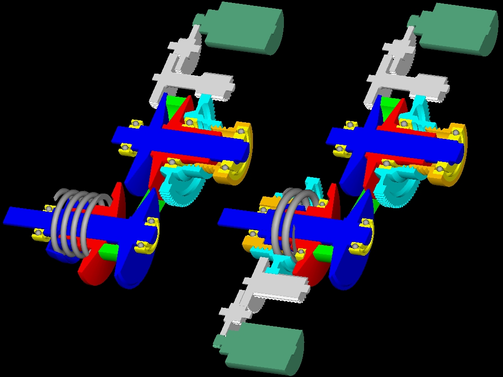
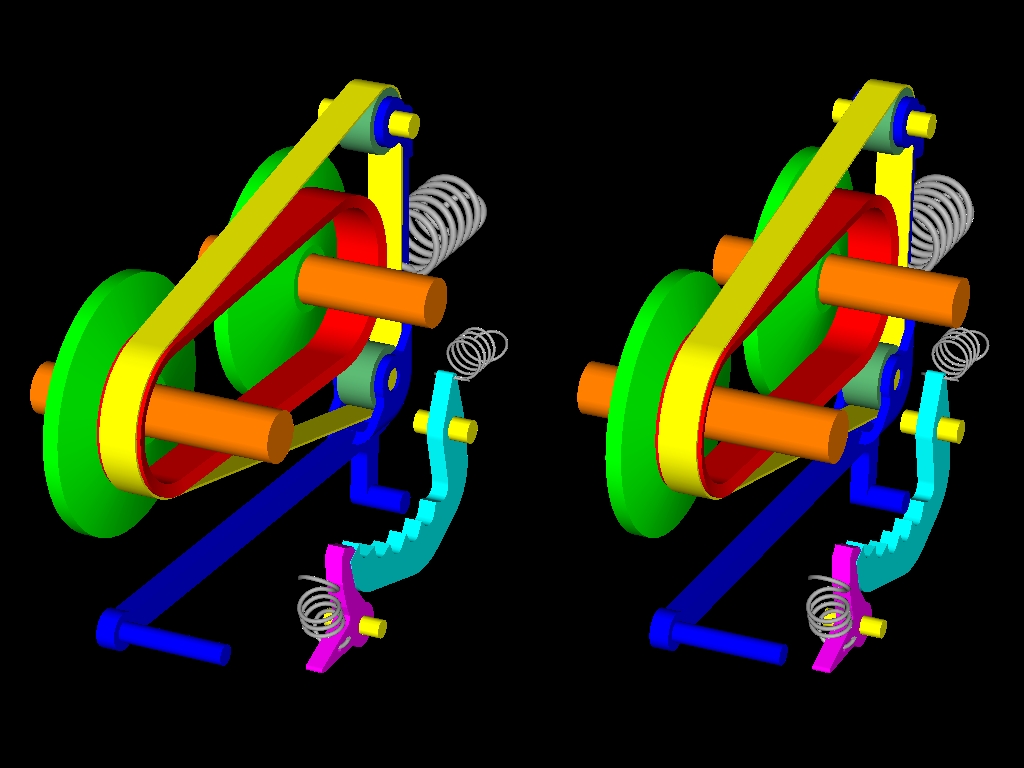
In the following stereoscopic drawing (the one conical half of each pulley is removed; click here to enlarge):
the previously mentioned pedal 15 (the cyan part with the cuts) is shown blocked by a lock (magenta) allowing the free motion of the lever 7 (blue); by unlocking the cyan pedal (all it takes is a light press on the front finger of the lock), the transmission turns to manual with seven distinct gear ratios (six from the cyan pedal, plus the longest transmission ratio of the CVT).
When the rider wants to return to infinite ratios, he has just to press deeply the cyan pedal and then to release it; at its return (under the action of its restoring spring) the cyan pedal gets blocked again by the lock and the transmission returns either to the automatic infinite-ratios mode, or to the manual infinite-ratios mode.
By blocking or pressing the front end of the blue lever, the rider selects manually a transmission ratio from the infinite available.
By completely releasing the blue lever (the restoring spring of the blue lever, at the back, keeps the auxiliary belt in tension) the rider leaves the transmission to operate automatically.
Strengthening (or weakening) the restoring force that acts on the blue lever (by shifting the anchoring end of the restoring spring of the blue lever, for instance), the characteristic curve of the CVT varies: in order to increase the effective diameter of the drive pulley, the variator has to compress (by means of the V-belt) the spring of the driven pulley as usual, but it has also to displace angularly the lever 7 overcoming a stronger (or weaker) restoring force.
It is like replacing "on the fly" the rollers of the variator by lighter or heavier ones.
In a two-mode version the rider shifts from the "touring" to the "sport" mode by pushing a pin (a button) to anchor a middle point of the blue lever restoring spring: the restoring spring becomes stiffer, a stronger restoring force acts on the blue lever and the variator keeps the revs higher.
As the SECVT (Suzuki Electronically-controlled Continuously Variable Transmission, of Suzuki, used in the Suzuki Burgman and in the Aprilia Mana, and regarded as the state-of-the-art CVT for scooters), similarly the PECVT (PatBox Electronically-controlled Continuously Variable Transmission) can, optionally, operate in a "manual" mode, too, wherein the driver / rider selects, by a button or lever, a specific gear ratio (from a set of allowable "manual" gear ratios).
Compare the complication, the cost, the loads on the parts and the functionally of the above two electronically-controlled CVT's (SECVT vs. PECVT).
The problem:
With the current low-cost CVT's the rider has not the option to select the transmission ratio of his desire.
The tuning of the CVT in the factory (geometry of the pulleys / belt / variator, mass of the variator's weights, springs used etc) is a compromise for:
relatively acceptable fuel efficiency (mileage),
relatively acceptable acceleration,
relatively acceptable final speed,
relatively acceptable reliability,
relatively acceptable climbing ability,
relatively acceptable NVH (noise vibrations harshness) properties etc.
However the user of the CVT may have different priorities, or
priorities that vary depending on the instant conditions (traffic, gradient of the road, "with or without" a passenger (total weight), opposite wind, need for quiet operation, need for top acceleration etc).
This explains the great demand for aftermarket variators.
With a different, or a modified, variator the CVT operates/behaves
differently.
By putting heavier weights (heavier "rollers") in the same variator, the revs of engagement drop, the vehicle runs quieter at lower revs, the mileage increases, the CVT is more reliable; however the acceleration drops, an opposite wind or a steep uphill may become significant problems, etc.
By putting lighter weights (lighter "rollers") in the same variator, the revs of engagement increase, the vehicle accelerates faster, the climbing on a steep uphill is easy, the strong opposite wind is not a problem; on the other hand the noise increases, the mileage drops, the time between overhauls drops.
Replacing the original variator by an aftermarket "sport" one is, more or less, like replacing the original camshaft of a car engine by an aftermarket "wild" one. With the wild camshaft the power at high revs increases in expense of a worse engine at medium-low revs (in terms of mileage, emmisions, smoothness, response, driver friendly operation etc). With the "sport" variator the CVT keeps the engine at different (higher in general) revs even when this is bad.
A long ride in the highway at 50mph (80Km/h) constant speed (wherein the "original" variator keeps the engine revving at, say, 5000rpm) is exhausting (NVH) as compared to the case wherein with a "mild" variator at the same speed the engine is revving at only 4000rpm. In the second case the engine runs at a heavier load (more open throttle) that decreases the specific fuel consumption and increases the mileage.
With a "sport" variator things get even worse: at the same 50mph (80Km/h) the engine is revving at, say, 6000rpm and the throttle is even more closed (even lighter engine load): more noise, more vibrations, reduced mileage.
In a fast ride, on the other hand, wherein the time and the acceleration is what counts, the "sport" variator is the winner.
The low cost automatic CVT's of the art are of the type: "take it, or leave it"; the user / rider has to compromise with the characteristics of the CVT.
Case study: "Overtaking with and without the PatBox"
A rider is cruising with his CVT scooter (and a passenger at the back seat) on a narrow country road at 50mph (80Km/h).
The engine is revving at 5000rpm (wherein it provides its peak torque).
The CVT operates at an intermediate point of the p3-p4 line of the "revs vs. speed" plot:
The rider needs to overtake a long truck in front of him.
All he can do is to completely open the throttle and to wish good luck.
The CVT keeps the revs at 5000rpm and the scooter accelerates, but not as fast as the rider wishes. Every tenth of a second is vital / crucial.
The same rider is cruising with his modified to PatBox CVT scooter (and the same passenger at the back seat) on the same narrow country road at the same 50mph (80Km/h) speed.
The engine is revving at the same 5000rpm (wherein it provides its peak torque).
The CVT operates at the same (as before) intermediate point of the p3-p4 line of the "revs vs speed" plot.
The rider needs to overtake a long truck in front of him.
Instead of wishing good luck, the rider has now the option to use the PatBox lever as he opens completely the throttle valve:
During the overtaking the rider (by means of the lever of the PatBox) keeps the engine operating at, say, 8000rpm wherein it provides its peak power; the time required drops substantially (for several seconds in some cases); the distance required to overtake the truck drops considerably, too.
The PatBox offers several options. The fact that it can minimize the time for an overtaking justifies, alone, its use.
Case study: "Application on a bicycle"
Replacing the variator by a spring that pushes close to each other the two conical halves of the drive pulley, the PatBox CVT is ready for use in bicycles.
The drive pulley replaces the front sprocket of the bicycle, the driven pulley (with its spring) replaces the rear sprocket of the bicycle and the V-belt replaces the chain.
An auxiliary belt rides around, and abuts on, the V-belt (at the side of the pulley with the stronger spring); the auxiliary belt rides, also, around rollers on a lever.
If the spring of the drive pulley is the strongest, when the lever 7 is released, the PatBox CVT restores at its longest transmission ratio (the two halves of the drive pulley are close to each other).
If the spring of the driven pulley is the strongest, when the lever 7 is released, the PatBox CVT restores at its shortest transmission ratio (the two halves of the drive pulley are apart from each other).
The rider by displacing the lever varies continuously the transmission ratio.
The rider starts pedaling as usual.
When the rider needs a shorter (or longer) transmission ratio, the rider turns (or releases) the lever 7, the lever 7 rotates for a few degrees and then is secured till the next gearshift.
A simple variator
A simple variator (the V-belt section is cross-hatched; the weights - or rollers - are spheres moving along grooves: as the revs increase, the spheres move outwards increasing the effective diameter of the drive pulley):
In a few words:
The PatBox is a simple, mechanical, lightweight, cheap and reliable
mechanism.
According the previous analysis, by modifying to PatBox the CVT of a scooter (all it takes is an auxiliary belt and a lever with some free rollers) the rider, besides the full automatic operation, gets an infinity of additional manually-selectable "gear ratios".
The rider can either vary, "on the fly", the characteristics of the
transmission in order to meet the instant needs for acceleration,
quiet operation, fuel efficiency, mileage etc, or the rider can leave alone the CVT to operate normally / automatically.
Instead of "moving" along a line of the "rpm vs speed" plot, with the PatBox the CVT can "move" along the same line, but it can also "move" outside it, in the area above the line (like moving in two dimensions instead of one).
With a variator engaging at lower revs (by replacing the "rollers" by heavier ones, for instance) this area extends providing additional useful and necessary modes (like: smoother, quieter and more economic highway trips) without any compromise in the acceleration, response, final speed etc.
While the PatBox CVT can provide infinite additional modes of operation, it actually adds no friction; instead, with the additional modes of operation, the overall efficiency (the mileage) improves, making the CVT greener.
Besides, the PatBox CVT can "replicate" any aftermarket variator; this means that with an aftermarket variator (any aftermarket variator) the vehicle cannot go faster than with the PatBox CVT.


